Printable Version of Topic
Click here to view this topic in its original format
6G Celicas Forums _ Interior/Audio/Electrical/Wiring _ The Car Alarm Installation Help Thread
Posted by: Coomer Sep 9, 2004 - 11:25 AM
First off, when installing an alarm, it's important to note that installation is 90% or more of the alarm's effectiveness. You can buy a $500 alarm with hundreds of features but it won't deter a theif or stop your car from getting stolen if your alarm isn't installed well, while you can spend $50 and some time and have a car that's next to impossible to steal.
Always hide the wires as well as possible, and make them look factory, whether that means using electrical tape or wiring loom, or anything else. It may be a bit more work, but it'll be well worth it when your car doesn't get stolen because of your quality alarm installation.
Always mount the brain of the alarm in a hard-to-find location, as high up in the dash as possible. The brain of the alarm shouldn't be in a location where a theif can reach up from under the dash and rip it out in a few seconds. The same goes for starter-kill relay...the wires should extend long enough so that the relay can be hidden in an obscure location in the dash. Also, the siren should be mounted in a location where it's hard to find and hard to access. Multiple sirens, battery-backup sirens, and piezo sirens(the little ones that generate a painfully loud high-pitched siren noise) inside the cabin are generally a good idea.
First off, we'll go over some basic connections. Do not take this information(or any other wiring information found on websites, for that matter) as being absolutely correct. It's your responsibility to test these wires yourself to ensure that they're the correct wires.
Ignition
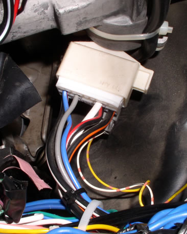
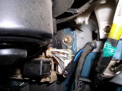
The ignition wires are used on nearly every alarm install, whether or not the alarm has remote start. These wires give +12 volts when the key is in the "on" or "start" position. At the ignition harness, one ignition wire is black/orange(Or possibly just black...I've read about two cars having their wire be just black instead of black/orange, so be sure to test the wires!) and the other wire is blue/red. Either of these wires may be tapped into for the ignition wire of your alarm. For remote start, both of these wires will need to be tapped into(your alarm installation manual will further explain this.) Both of these wires are fairly thick and reside in the ignition harness, which is located behind the ignition switch. The ignition harness is shown below.
[attachmentid=88]
Starter
This wire is used for remote start and for starter-kill, which is when the car won't start if the alarm is armed. The starter wire in a sixth generation Celica is black/white, and is located at the ignition harness. Like the ignition wires, it's a fairly thick wire.
Constant +12 Volts
This wire is often used for the constant power in remote start installs. It's black/red, and is located at the ignition harness. Also, you could tie into this wire for the constant battery power for the alarm itself. That way, there wouldn't have to be a wire running directly from the battery to the inside of the car, which would make it harder for a theif to kill power to the alarm brain. If you do splice into this wire for an alarm install, be sure to use an inline fuse.
Parking Lights
If you want your parking lights to be integrated with the alarm, you can hook up the parking light wire from the alarm to the dark green wire that connects to the dimmer switch. The dimmer switch can be easily accessed by pulling off the panel that goes above and around the steering column. There are only clips holding this panel on, so it just pops right off, exposing the wires for the dimmer switch.
Door Trigger
The door trigger wire on sixth generation Celicas gives a ground signal when either door is opened. This wire is commonly used so that alarms can go off when a door is opened and the car is armed, or to warn the user that a door is opened when the user arms the car, or it can be used for many other uses. This wire is red/white, and is looped out of the car's harness, right behind the driver's side kick panel underneath the door sill.
RPM Signal Wire
For some remote start installations, tapping into the car's RPM signal wire is required or recommended. The RPM signal wire is located at the ECU, and is a black/yellow wire at the ECU. The ECU is located in the center of the car on the raised part of the floor right next to the firewall. The wires are accessible on the passenger-side of the ECU, and are accessible if you pull down the carpet in the passenger footwell a bit. To test this wire, you need a multimeter in AC mode. The wire should give out between 1 and 6 volts AC, and increase when the RPMs on the car go up.
Door Lock Wires
I don't have power door locks in my car, so I'm strictly going off research that I've done on this one, but the sixth gen. Celica's door lock wire should be blue/black, and the unlock wires(there are two of them, and they need to be diode isolated) should be blue and green. These wires can be found at the door lock module, which is to the right of the steering column. The wires are negative triggered, meaning that to lock or unlock the doors, the correct wire(s) needs to be given ground. To test that these wires are correct, test for ground on these wires with a multimeter. When you lock the car with the switch on the door, the blue/black lock wire will give ground for a brief period of time. The same goes for when you unlock the door, except the wire will be the blue unlock wire and the green unlock wire instead. To diode isolate the wires for the unlock wire, you'll first want to split the unlock wire coming from the alarm. Then, you'll want to install a diode in each wire with the cathode on the alarm side(For more information on diodes, please go http://www.the12volt.com/diodes/diodes.asp.), and then a wire connecting the anode side of the diode to each door unlock wire.
Power Window Wires
In some installations, a power window module is used. This module allows your alarm to control your windows on your car. For example, your windows could be set up to roll up when the car is armed, or they could be set up to roll down all the way when you activate an auxilary channel on your alarm. When installing a power window module, the wires that you want to control will need to be cut. For example, if you want your windows to roll up when the car is armed, the window up wire for each window would need to be cut, and then one wire from the power window module would connect to the switch side of the wire, while another wire from the power window module would connect to the window motor side of the cut wire. There are also connections that need to be made for a power window module, but the module's manual will discuss those in further detail. The power window up wire for the driver's side window should be green and is located at the driver's side power window switch. The power window down wire for the driver's side window should be red and is located at the driver's side power window switch. For the passenger window, the wires can be found in the driver's side kick panel, and the up wire should be green/white, while the down wire should be red/blue.
Running Wire
For whatever reasons, sometimes it's necessary to run additional wires into the doors. Bigger speaker wire, wire for aftermarket door lock actuators or aftermarket power windows, power wire for neons, etc. all require new wire to be run into the doors. The proper, clean way to do this is to simply run the wire through the rubber tubes where the factory wires run through.
The first step is to remove your door panel. There are two screws near the front of the door(closest to the dash), four screws on the bottom of the door, three push-in clips on the rear of the door, one bolt in the bottom of the armrest, a screw that holds the panel behind the door lever in place, and another screw behind that panel. If you have a window crank, that too must be removed, and the window crank is held in place by a bent piece of metal that pops out. Also, the triagular panel on the top of the door panel must be removed. It simply pulls out. All of these must be removed, and then the door panel will swing open on the bottom, and then will simply pull up. Don't forget to disconnect the harnesses if you have power windows or door locks.
Once the door panels are off, you'll need to remove your speaker closest to the front of the door where you'll be running wires. This will allow you to get your hand behind there to run wires. You'll also want to remove your kick panel covers, which is as easy as pulling up the door sills, taking out the single plastic nut that holds the kick panel in place, and pulling the kick panel out.
Once everything is removed, you'll need to cut part of a coathanger and straighten it. With the coathanger, bend the end approximately 180 degrees so that it forms a rounded end and you've got about one inch of metal bent back towards the coathanger. Now bend the rest of the coathanger so that it has a gradual curve. This will allow the coathanger and the wires you'll attach to it to easily go through the rubber tubing.
[attachmentid=89]
Once the coathanger is bent, attach some wires near the rounded end of it with some electrical tape. Make sure that you have no large bumps or anything of that sort that will cause the coathanger and wires to get caught on anything. Once the wires are taped on, start from the inside of the door and push the coathanger gently through the entrance to the rubber tube and through the rubber tube into the interior of the car. It helps to wiggle the rubber tubing with your hand while you're running the wires through it to ease the coathanger and wires through. Be sure not to force the coathanger if it won't go any further...you can always bring it back a bit and try again.
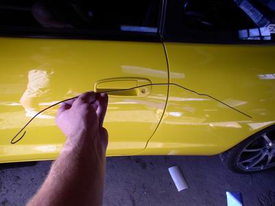
Once you can see the wires and coathanger in the kickpanel area of the car(pictured below), you can unwrap the tape, and then pull the coathanger completely through the tube. At this point, you've got wires from your door now inside your car. Simply carefully pull the wires through with your hand until you've got the wire where you want it, and you're done. You should now have wires run cleanly through the rubber door tubes. 
[attachmentid=90]
No Factory Power Door Locks? No Problem
If you don't have power door locks, you can always install aftermarket power door lock actuators. A common place to find them is eBay(Just search for "door lock actuators" or "power door lock.") If you get the power door lock actuators with two wires coming from each actuator, then you can simply wire them up as shown in the wiring diagram below(Thanks to The12Volt.com for the diagram.)
[attachmentid=87]
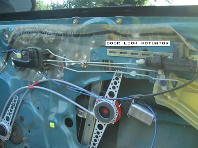
Mounting the door lock actuators is fairly easy, and simply involves drilling two holes, attaching the door lock actuator to the inside of the door, and then hooking up the rod coming from the actuator to the car's factory door lock rod. A photo of how I did this is below.
[attachmentid=86]
Powered by Invision Power Board (http://www.invisionboard.com)
© Invision Power Services (http://www.invisionpower.com)