Printable Version of Topic
Click here to view this topic in its original format
6G Celicas Forums _ Engine/Transmission/Maintenance _ How to: 3S-GE BEAMS Wiring into USDM Celica
Posted by: richee3 Dec 21, 2013 - 11:16 PM
I've been thinking I need to do this for a while now, but Dustin and Manny inspired me to do it in the podcast tonight.
This information is comprised from various threads with the help of Batman722, hurley97, njccmd2002, turnip, erahman, and others. I will continue to update this thread with better pictures and details as the need arises.
Important information before you get started:
1. This thread is a general guideline, NOT a 100% direct how-to! This is what was necessary to get my BEAMS going in my 1998 USDM ST204. Other changes may be necessary on different models.
2. As always, this thread is for information purposes only. I cannot be held responsible for any accidents, injuries, or any damages that may occur during an engine swap.
Now that that's out of the way, lets get started. First things first, here's a helpful link for how to remove wires for the plugs in your wiring harness.
http://www.6gc.net/forums/index.php?showtopic=92693&pid=1046398&st=0&#entry1046398
You have two options for routing the engine harness. Since the BEAMS came in a right hand drive Celica, the harness goes through the opposite side of the firewall. This means the harness is too short to go through the same place in the firewall that the 5S harness goes though. You have two options: 1.) To properly extend the harness to reach the stock hole or 2.) to cut a new hole in the firewall.

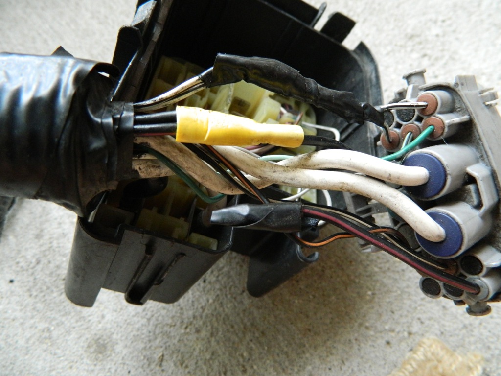
When you remove your old engine, you'll see a large gray plug in the fusebox under the hood. This is the EA1 plug. If you look very closely where the wires run into the plug, you'll see some very small numbers printed next to each wire on the plug itself. These denote which pin you are working with.
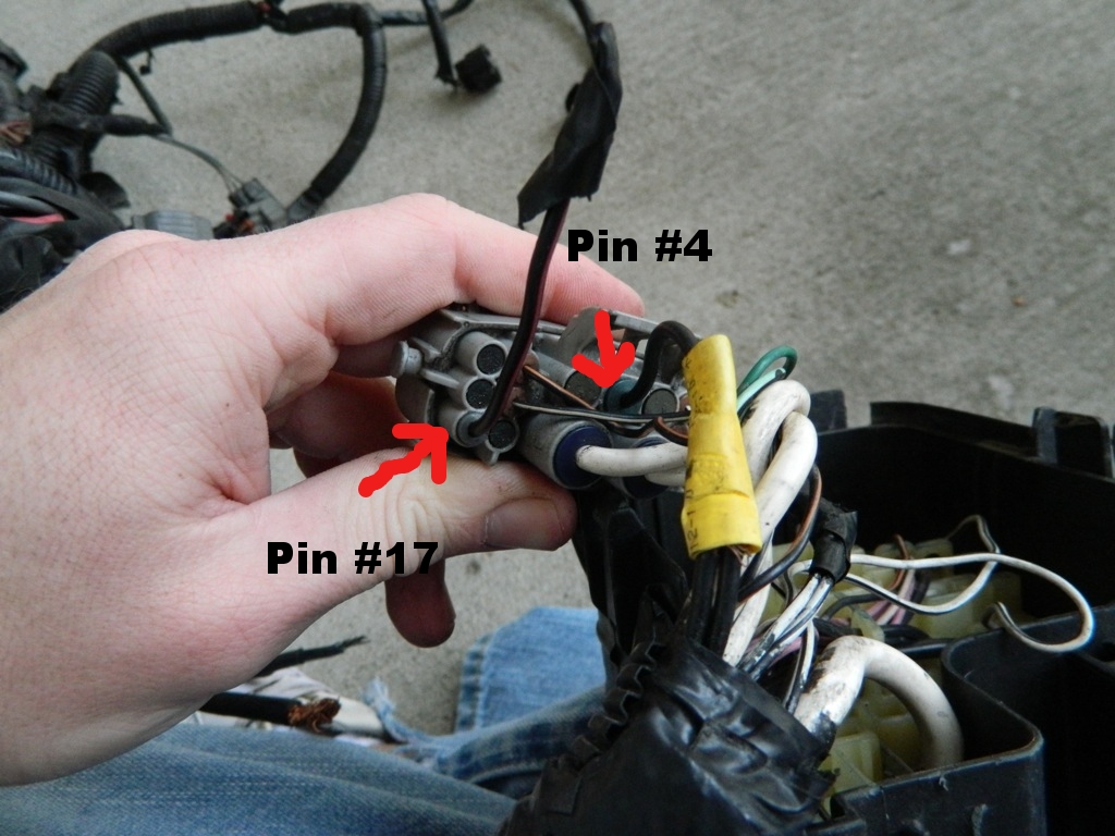
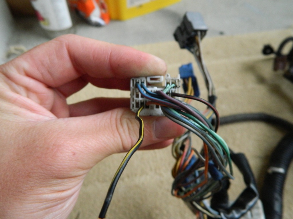
EA1 Plug: Pins 17 and 4 need to be bridged. Pin 4 needs power when pin 17 has it. Pin 4 is the big black wire at the top, center of the plug. Pin 17 is in the lower left corner, black w/red trace. Doing this gives the BEAMS spark. Pin 17 coming off of the EA1 plug can be snipped and covered up, left alone. (See picture 1.)
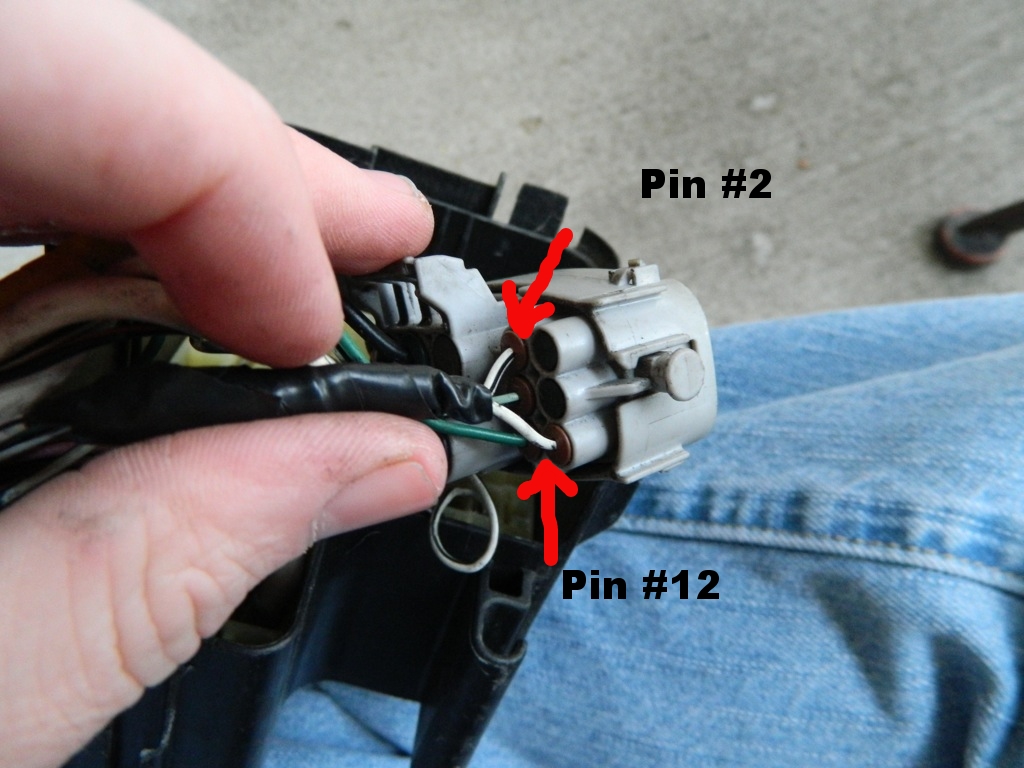
EA1 Plug: Pins 2 and 12 need to be bridged. They are both ground wires, white w/black trace. (See picture 1.)
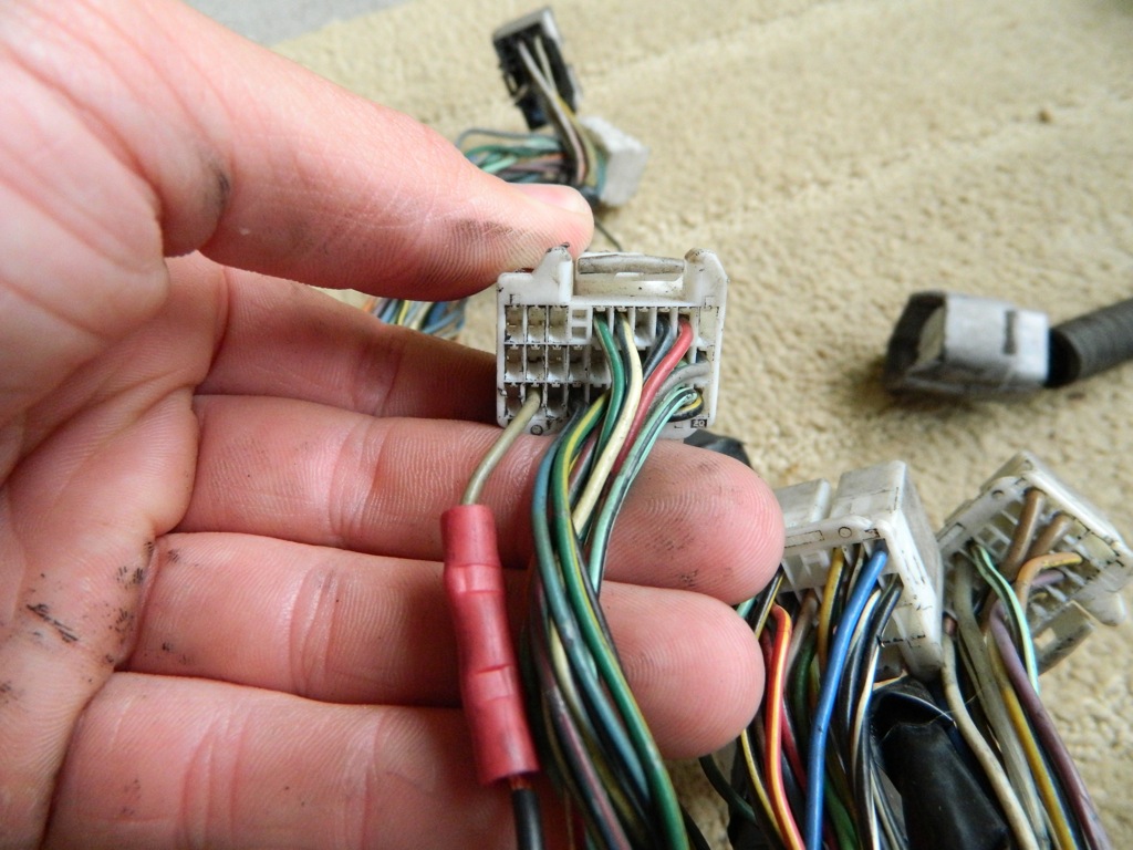
Clutch start wire: Black w/yellow trace. This one is a bit tricky to explain. There are 3 vertical plugs next to the ECU. On the body side of the plugs, you have a white (19 pin) plug, light gray (13 pin) plug, and dark gray (17 pin) plug. The clutch start wire is pin 18 on the white plug. Move it to pin 17 on the dark gray plug. (Refer to picture 2.)
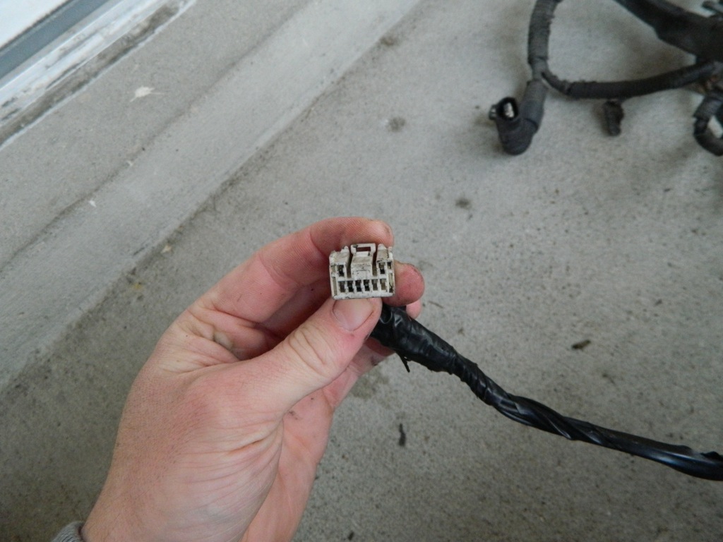
If using your OEM tach and a tach adapter, you'll need to intercept the tach signal going from the ECU to the gauges. This comes from plug C, wire 27 on the ECU plugs. It's a gray wire. (Refer to picture 3.)
Cruise control wiring: I have a 1998 USDM Celica. In my case, no wiring changes were necessary and my cruise control works perfectly. I believe that this is standard across the board of USDM Celicas, although some pre-98 models may still require changes. Further research from others is necessary.
Airbag light: To get your airbag light to function properly, you run a wire from the EA1 plug to the light gray interior plug (either pin 4 or pin 5, I have read separate posts saying both and I chose not to do this step so I cannot confirm which pin it is.)
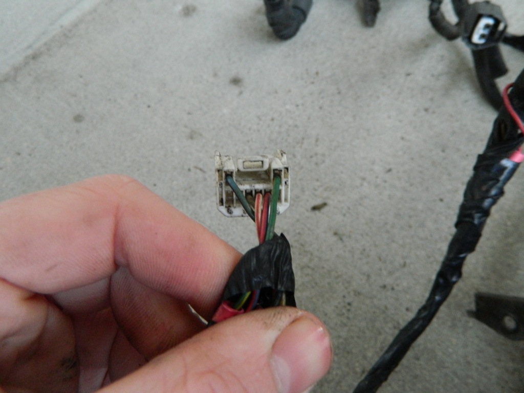
A/C amplifier- There's a 3 or 4 wire plug that plugs into the A/C amplifier behind the glovebox. If you run your harness through the firewall, this needs to be extended. There's no way around this. However, if you choose to run your harness through the OEM location, it will not need to be extended.
Picture 1. EA1 plug: At the top, pins 2 and 12 are bridged together. These are grounds. In the middle with the yellow butt connector, you can see pins 17 and 4 bridged together, red w/black trace and plain black wire. At the bottom of the picture, you can see the unused and covered wire that used to be pin 17.
Picture 2. Body plugs next to the ECU. Here you can see the clutch start wire in the bottom left corner, black w/yellow trace.
Picture 3. Plug C, wire 27. This is the tach signal wire that needs to be intercepted for a tach signal adapter.
Picture 4. A/C amplifier plug that must be extended if you choose not to extend your harness.
The pictures show my early attempts at wiring, with butt crimps instead of proper soldering. I do not recommend butt crimps at all; if you do the wiring changes, I highly recommend taking a few extra minutes to properly solder everything so you don't risk any connections coming loose, not to mention how much neater and cleaner it is.
After you have made these changes to your harness, you should have a properly running BEAMS in your USDM Celica. Of course, you cannot use your OBDII any longer as JDM ECU's use a different protocol and USDM scanners cannot read the codes. You have two different options at this point: You can pull your codes and count the number of times the check engine light flashes then refer to this thread:
http://www.mr2.com/forums/threads/67398-Toyota-Code-error-%28all-models%29
OR:
http://www.6gc.net/forums/index.php?showtopic=89746&hl=
Feel free to add to this thread. I will add any pictures or any other information you guys come across, and feel free to let me know if there's anything that I missed.
Happy swapping!
Posted by: Smaay Dec 22, 2013 - 3:09 PM
excellent post! The only comment I have is conform the signal to the wire. In my years of wiring toyotas, color code does not always match and pin location does not always match. Im finding diagrams swapping signals.
specifically RSC and RSO. one 3S-GTE diagrams had them swapped from another.
Posted by: richee3 Dec 26, 2013 - 2:28 AM
Extending the harness: To extend or not to extend?
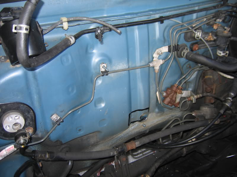
As previously stated, the wiring harness on the BEAMS was intended to go through the opposite side of the firewall than what it does on USDM Celicas, making the harness simply too short to go through the same routing as the 5S-FE or 7A-FE engine harnesson our USDM left hand drive Celicas. One way to get around this is to cut a hole in the firewall, as so many 3S-GTE and BEAMS owners, myself included, have chosen to do. See the picture below for a general reference of where to cut the hole.
That photo comes courtesty of Batman722 from his 3S-GTE swap thread. Again, DO THIS AT YOUR OWN RISK. ALWAYS, ALWAYS, ALWAYS measure twice and cut once, make sure there are no flammable fluids in the area (fuel lines will have been opened prior to this), check both sides of the firewall to ensure that you are not cutting anything valuable such as your dash harness, and proceed with extreme caution.
Choosing to run your harness through the firewall means that you will need to extend a four wire plug for the A/C amplifier. Its the plug that plugs in underneath the glovebox when you unplug and remove the engine harness. Its very possible that you may be able to pull enough slack to not extend your plug, but myself and others had to extend those few wires before we could make the plug reach.
Obviously going this direction means that you will have an open hole where the original harness used to be. I used a small piece of plexiglass and a small piece of Frost King foam duct insulation to cover that hole, drilling holes through the plexiglass and using the nuts that originally held the engine harness in place to secure the plexiglass. The Frost King was between the firewall and plexiglass to insulate for noise and keep uwanted bugs, heat, etc. out of the cabin of my car. I was never happy with that solution due to the cheap look, but I already had the materials sitting around. I could have spent under $10 to pick up a thin piece of sheet metal and achieved a much cleaner look to seal the hole off.
Option #2: Extending the entire engine harness to follow the original USDM routing through the original hole.
Know this before you get started: If you cannot solder or do not have a friend who can properly solder wires together, you are better off going with the first option. If you arent afraid of tackling this project yourself, be sure to buy some solder, a soldering pen, some wire, and some heat shrink tubing to make a few test joints before tearing your wiring harness apart.
After a short period of time, I decided I didnt like how I had ran my harness. By this point I had bought a second BEAMS Redtop so I had a spare wiring harness to play with. I decided I would try my hand at extending the harness to emulate the USDM wiring routing. I opened a small section of the wiring room about 6 before the harness enters the firewall and I got to work extending every single wire about two feet. This was entirely too much and leaves me with a lot of slack in my harness in the engine bay. 18 would have been much better and may still be too long. This only shows that it never pays to assume- you should take a proper measurement before extending your harness like I should have.
Please note: There are a few shielded wires in the BEAMS wiring harness. I extended mine but njccmd2002 did not have to. Please read below.
Had I read njccmd2002s thread again before diving into this project, I would have known that I did not need to extend all ~60 wires. He was able to unloom his harness completely and pull enough slack out of most of his wires that he only needed to extend roughly 25 wires. Im sure he can elaborate on this. See his pictures below.
http://s254.photobucket.com/user/njccmd2002/media/6th_Generation_Celica/97_Limited_Edition/Beams_Engine_Swap/IMG_6030.jpg.html
http://s254.photobucket.com/user/njccmd2002/media/6th_Generation_Celica/97_Limited_Edition/Beams_Engine_Swap/IMG_6035.jpg.html
Another pic where you can see after the firewall entry no cable was extended. And extended the maf and the vsv? Can't remember...
http://s254.photobucket.com/user/njccmd2002/media/6th_Generation_Celica/97_Limited_Edition/Beams_Engine_Swap/IMG_6138.jpg.html
Only plugs I extended...
http://s254.photobucket.com/user/njccmd2002/media/6th_Generation_Celica/97_Limited_Edition/Beams_Engine_Swap/IMG_6038.jpg.html
He did indeed need to extend the wires for the MAF and the VSV, as did I. Again, it isnt terribly difficult, especially not if you only cut and solder one wire at a time.
If you are someone who enjoys things neat and tidy, you can get a spare engine harness, perhaps even the harness that you pulled out with your old engine, to reclaim wires of the same color scheme as that you will be extending on the BEAMS harness. At the time, I chose to use plain black generic wire. Now I wish I had matching color schemes, but it isnt that important.
For anyone attempting to swap a BEAMS, I highly suggest taking the extra time to take your harness apart and extend everything. I spent a handful of hours extending every wire in my harness, where njccmd had a much smarter method and discovered that only a few wires need to be extended. Using the original hole in the firewall is much cleaner in my opinion, and doesnt leave you with a hole in your firewall that you need to seal off. I have made a lot of mistakes when I first started swapping my car, and I have spent too many hours to count and more money than I care to know trying to correct my mistakes. Hopefully this thread can save a few of you guys from repeating my mistakes.

Posted by: mgnt232 Jan 3, 2014 - 5:29 AM
Awesome post! Now when i get around to doing the swap I can pretty easily just look at this.
I paid a boatload for the 3sgte harness and it still threw the code 54 which i had to figure out myself. Even though the info is here on 6gc, it was spread out over a lot of posts and no one really confirmed if what they did worked. I assume they just got it working and called it a day, not bothering to post what they did.
Will deff use this when i do my future swap in the red celi. Makes everything soo much easier when you dont spend your time searching...and searching..
and congrats on being a mod
Posted by: njccmd2002 Jan 3, 2014 - 8:16 AM
what is code 54 anyways? yes i dont know, i dont have a real engine.. too lazy to search, and i bet others are too...
Posted by: cardshark525 Jan 3, 2014 - 10:53 AM
Code 54 relates to the intercooler.
The two most common causes are the intercooler level sensor, or a faulty intercooler water pump.
In the first case, the ecu isn't able to tell if the coolant level in the intercooler is low, so it assumes it is (if the car cant figure out what's wrong, it plays it safe). Most people simply bridge the two wires, ecu assumes it's full now and the problem is solved. If this is done the most obvious thing to be sure to do is to regularly visually check your coolant level.
In the second case your pump and or wiring (my case) is faulty. If this is the case your coolant isn't actually being circulated through the system which will lead to heat build up and added heat is never a good thing for either reliability or performance. The solution here is obviously to change the pump.
Code 54 is also the most common code with the 3sgte and from what I've read on the forum is almost guaranteed to pop up. Just a matter of diagnosing it and fixing it from there.
Posted by: njccmd2002 Jan 6, 2014 - 9:39 AM
one question for the ST owners? i read somewhere an issue with the radiators somewhere, where the st does not have a temp sensor, this was swapping a 3sgte... would this apply to the beams, or not..
Anyone that has swapped a beams into an ST may want to chip in...
Posted by: Batman722 Jan 6, 2014 - 12:23 PM
Anyone that has swapped a beams into an ST may want to chip in...
For either swap you would need (or should use) a GT radiator with the temp sensor on the bottom. The GT rad has the water inlet and outlet in the correct spots also. STs have the temp sensor wiring in the engine harness where the GT is part of the chassis harness. The neato thing is the ST has the temp sensor wiring in the chassis harness as well, the plug is taped up near the bottom of the rad.
The solution, use a GT rad with the temp sensor, and it's plug and play with an ST.
FYI the temp sensor on the bottom of the GT rad is only for the temp gauge on the dash, the ST has that temp sensor on the thermostat water neck, not in rad, but does the same thing.
Posted by: Smaay Jan 6, 2014 - 1:41 PM
Dustin i think you are incorrect about the sensor to the gauge. Typically the gauge is a single wire sensor like the one in this pic. here you see the 2 wire sensor for the ECU and the single wire next to it for the gauge. im really not sure what the sensor on the radiator is for.
then again i might be all wrong, im just going off memory here.
edit: now im 100% sure the gauge is the single wire on the waterneck, tuning Amy's car over the weekend the temp gauge never moved, check the sensor and the plug had come off. plugged it in and boom, normal temp reported.
Posted by: Batman722 Jan 6, 2014 - 1:56 PM
That's correct, the st has it on the waterneck, the gt has the sensor in the rad.
Jeff, just to verify, see if that st has the plug (unplugged) pass side, near the bottom of the rad for a gt rad.
Posted by: Smaay Jan 6, 2014 - 4:13 PM
this picture is of a 99 GT
Posted by: Batman722 Jan 6, 2014 - 4:56 PM
Understood.
I was on my phone and couldn't see the pic that well.
I was wrong, the temp sensor on the GT rad is for the fans, not for the gauge. The sensor for the fans is on the waterneck for the ST.
If you swap a 3s using the 3s harness and you do not use that sensor (in the GT radiator) your fans will be on when the car is on. As I said the wiring is there for it, just use a GT radiator with the sensor, then plug it in, no issues.
Posted by: mkernz22 Jan 6, 2014 - 7:17 PM
Actually the sensor on the water neck is the one that goes to the gauge on the dash for the GT's. My wire just broke on that sensor and I wasn't getting any reading on my gauge. Spliced in a new plug to the sensor on the water neck and the temp gauge works again.
Posted by: richee3 May 12, 2014 - 8:46 PM
BEAMS Redtop Wiring Pin Guide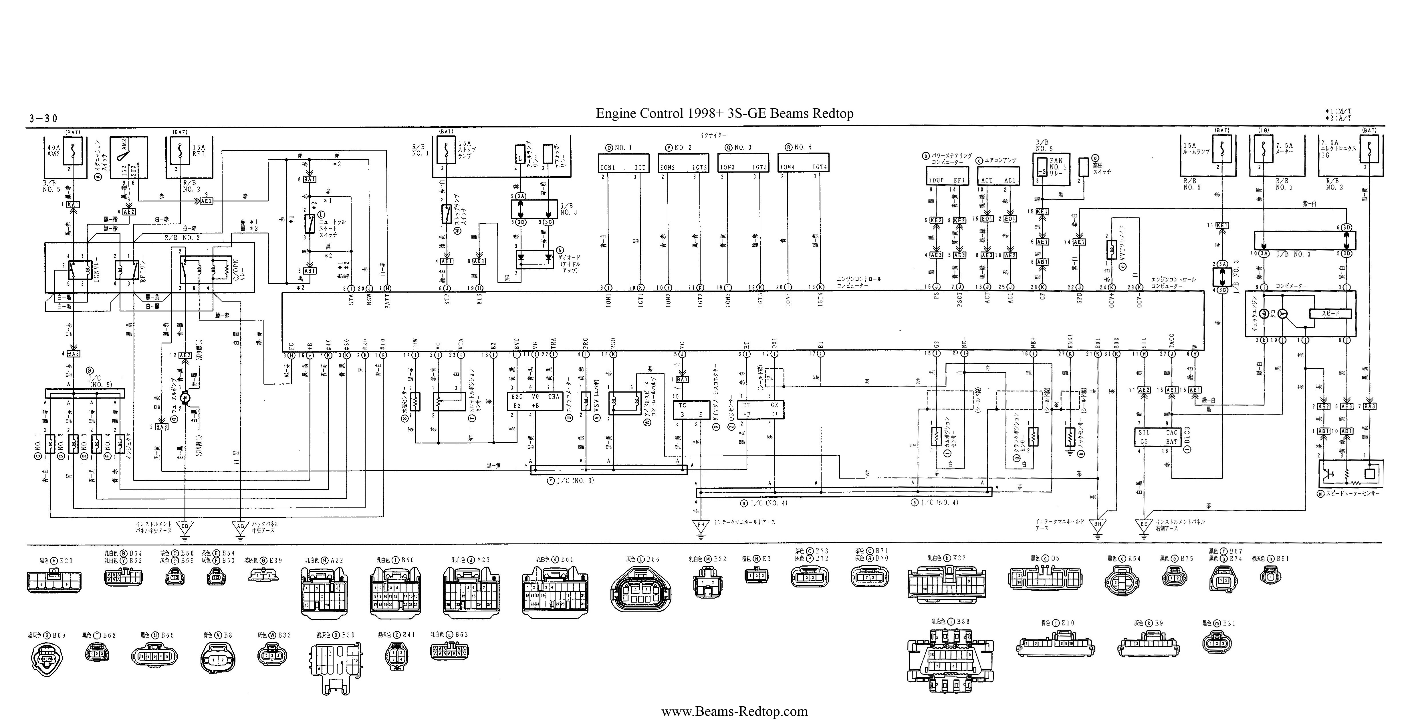
Same picture, translated: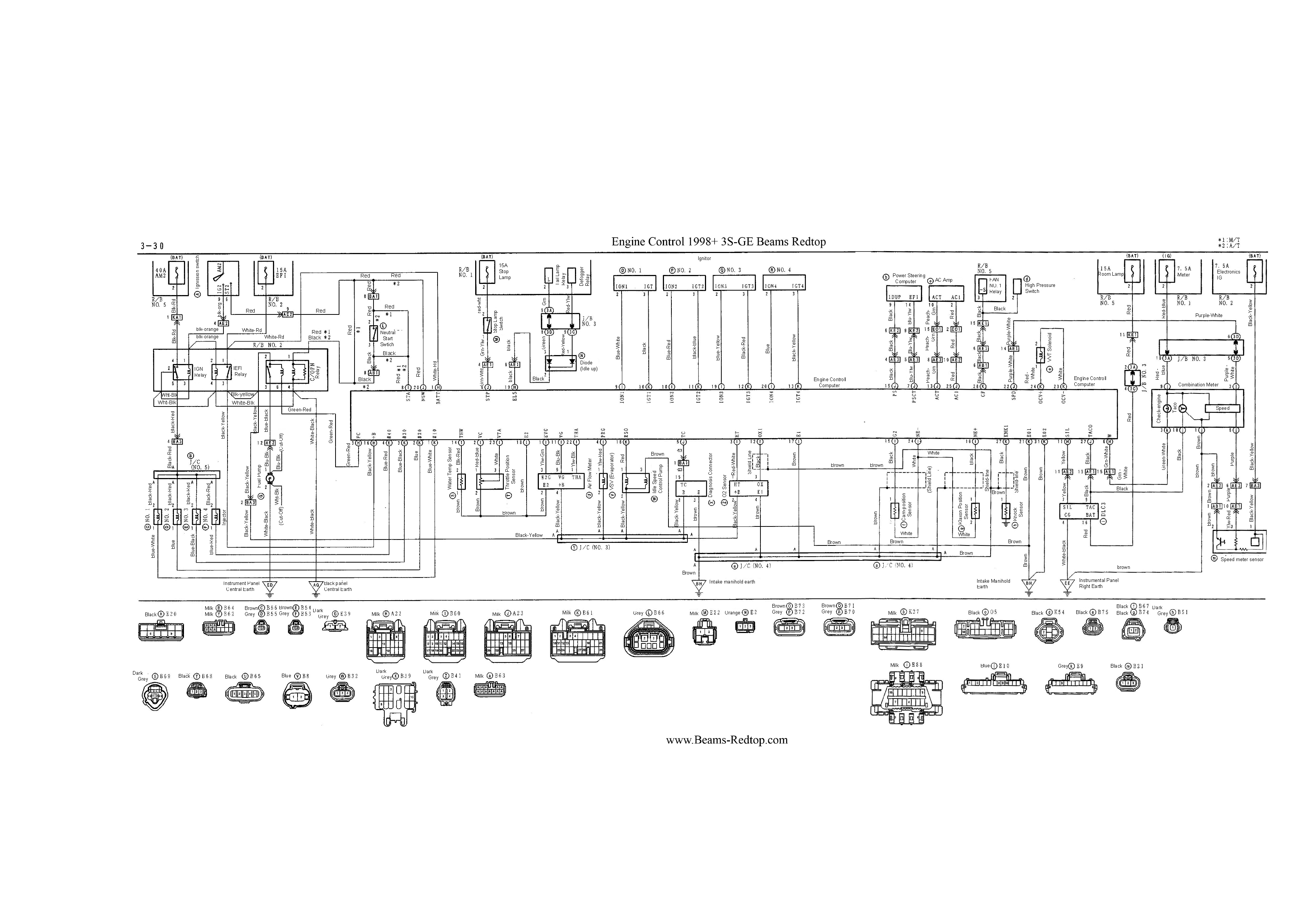
ECU Pinout: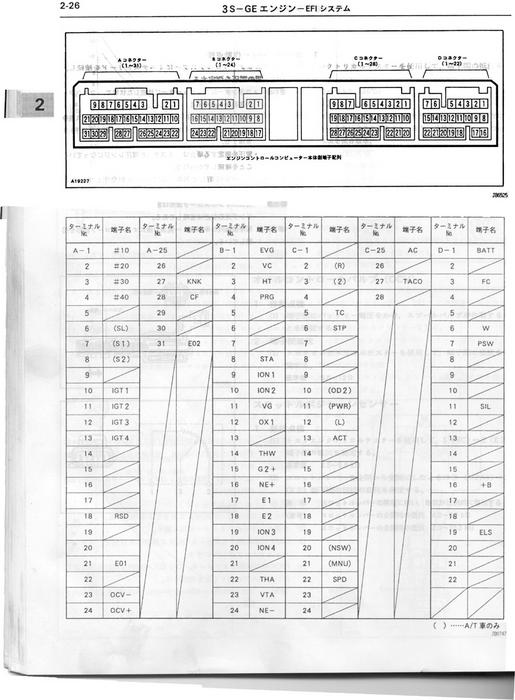
Posted by: njccmd2002 May 12, 2014 - 10:01 PM
ill get some pics of my beams as it lays outside to show how i guided the wires...
Posted by: njccmd2002 May 15, 2014 - 8:24 PM
this pics can be moved to the top.
this is where i routed the harness. i did not cut and weld all wires, but only a few, i rerouted the rest, i think i even left the knock sensor wire intact...
http://s254.photobucket.com/user/njccmd2002/media/6th_Generation_Celica/96_26th_Anniversary/General_stuff/DSCN1062_zps228113aa.jpg.html
close up...
http://s254.photobucket.com/user/njccmd2002/media/6th_Generation_Celica/96_26th_Anniversary/General_stuff/DSCN1061_zps7b83b82f.jpg.html
this when i added the needed wires, which was only half of the harness., it ended being not so thick..
http://s254.photobucket.com/user/njccmd2002/media/6th_Generation_Celica/96_26th_Anniversary/General_stuff/DSCN1067_zpse1f78ab8.jpg.html
Posted by: Over9000 Jul 17, 2015 - 12:58 PM
Has anyone ran into the issue of not having pins 17 or 12 on their ae1? In that case would I be able to bridge it before the connector on the other side? Or should I add a pin to those?
Posted by: richee3 Jul 17, 2015 - 9:45 PM
Are you looking at the BEAMS or 7A harness? Pin 12 is just a ground wire and it seems like I recall another BEAMS owner saying they didn't have it or didn't need it, so I wouldn't worry too much about that one. Just keep it in mind in case you have any issues later. However, Pin 17 and 4 is necessary for the BEAMS. Pin 4 gets power from the wire for pin 17. I'm sure you can bridge them after the fuse box in the chassis harness, but I would think it's easier to convert the engine harness to work in the chassis instead of making changes to the chassis harness.
Posted by: Over9000 Jul 17, 2015 - 11:53 PM
I'm looking at the 7A harness. That's where my BEAMS engine harness ends and my 7A chassis harness begins. We're supposed to bridge the wires after the box I thought...
When you said "When you remove your old engine, you'll see a large gray plug in the fusebox under the hood. This is the EA1 plug." I assumed it was the plug still in the car, correct?
Posted by: richee3 Jul 29, 2015 - 8:32 PM
Whoa, just now realized I forgot to reply to this post. I read your question right before going to sleep one night and meant to respond in the morning. The EA1 plug is in the engine harness, not the chassis harness. All the modifications to the harness will be done to the harness that came with the engine. The 7A's engine harness is now useless, and can be sold or scrapped with the engine. The chassis harness can be left alone and unmodified.
Posted by: Tigawoods Feb 25, 2016 - 8:20 AM
Just a quick note that should probably be highlighted. I kept forgetting to bring it up.
I didnt feel like going through the guide again to confirm but I am pretty sure this is how it goes:
The wiring guide has the IGN and EFI connected at EA1 plug or somewhere around there, which means when the EFI plug is pulled (compression testing reasons or fuel/spark testing) both the Fuel system and Ignition system are cut off from power. Ideally it would be nice to get these two on separate fuse systems but thatd be a bit more work.
I just thought itd be worth noting that wiring these two together may cause some confusion down the line if the person doesn't realize that they are wiring the two systems together.
Posted by: Chrisss6g Apr 19, 2016 - 3:35 PM
Dose anyone know the gauge cluster diagram for the 3sge redtop beams engine really would help mph or rpm or temp doesn't work
Posted by: richee3 Sep 23, 2017 - 11:45 PM
All pictures that I have access to have been fixed- permanently. No worrying about any third party image hosting issues. Norberto, do you still have the pictures of extending your BEAMS harness?
Posted by: njccmd2002 Sep 23, 2017 - 11:59 PM
temp post, looking for pics..
IMG_6030.jpg
IMG_6035.jpg
IMG_6138.jpg
IMG_6038.jpg
Posted by: richee3 Sep 24, 2017 - 12:08 AM
You can text them to me if that's easier for you. No need to host them somewhere, since I will be hosting them here.
Posted by: njccmd2002 Sep 24, 2017 - 12:14 AM
lol go to bed... i have a way to look for them... im looking for them, i have to search by name, i will host them. cause i will try to bring back my beams swap post. no worries
plus i carry them in a thumb drive, so cant text, dont have them in my phone...
found them.... lol.. delete this post,,,,
Powered by Invision Power Board (http://www.invisionboard.com)
© Invision Power Services (http://www.invisionpower.com)