
 Jul 11, 2009 - 3:41 PM Jul 11, 2009 - 3:41 PM
|
 
|
|
Enthusiast  Joined Jul 11, '09 From UK Currently Offline Reputation: 2 (100%) |
Hi all i am curently installing cauto climate control in to a non climate control car so thats climate control out of a 1994 jdm Gen6 Celica st202 and installing it into a 1997 uk Gen6 gt st202.
does anybody know where to get a wiring diagram for the auto climate control system as i can only find one for a Gen5 st182 celica. heres hoping Pete |

 |
Replies
|
Aug 16, 2009 - 12:21 PM
|
|
|
Enthusiast Joined Jul 11, '09 From UK Currently Offline Reputation: 2 (100%) |
Right well i thought i would wright a how to so here goes
you will need. JDM parts A/C fan A/C compressor  smooth pulley for 3gse http://img.photobucket.com/albums/v79/cavegod/Photo-0051.jpg longer drive belt A/C pipe work 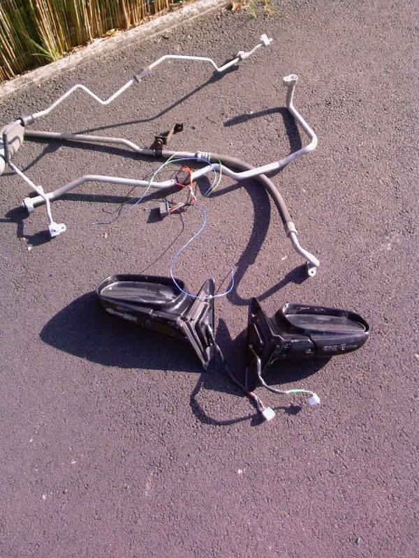 A/C radiator 3 relays heater duct assembly evapourater housing temp mixer cable 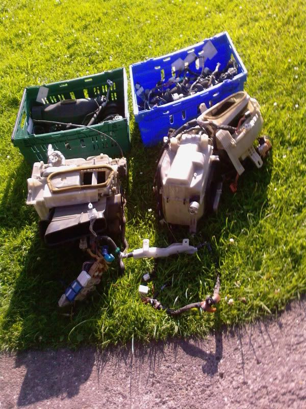 ambient temp sensor cabin temp sensor  solar sensor middle one  Climate control unit  CC wiring 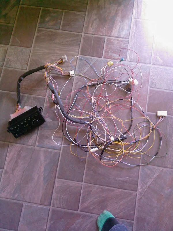 you will need the wiring on the evap and heater duct assemblies   if your car has Air conditioning you will need to swap a few things but for this mod take it as having no air con at all, the celica gen6 should have the wiring in place for normal aircon system so to make sure check for a few things behind glove box should be a large multiplug above the blower duct and a multiplug below blower ducting both will be taped to the wiring loom in the respective places. in the engine bay you should check for a grey connector taped up near the diagnostic port and one taped to the wires on the radiator pipe from the thermostat, and last but not least a plug taped up near the left hand relay box. once you have made sure you have them away we go! remove the dash board  with the dash board out of the way remove the metal tubular frame as well, then you can get to work. remove the following in engine bay disconect the heater hoses and mixer cable in the car remove the blower ducting and the heater duct assembly with those out the way you can start the install fit the JDM heater duct assembly thread the mixer cable through to the engine bay and heater hoses, then bolt it in and connect th ecable and hoses to their respective places. next remove the blanking panel from the bulk head and then bolt the evap housing in place. in th eengine bay fit the JDM plate over where the Evap pipe work enters the engine bay.  then fit all the engine bay A/C parts just a matter of bolting them in place, compressor torque is 25nm and all A/C pipes are 10nm. fit the A/C fan to the radiator using the three bolts and then plug it in as well as plugging in the compressor and the pressure switch. thats the engine bay done. next up is wiring the beast in! onc you plug all the multiplugs in you will be left with a few wires that need connecting. the following wires just need removing from the CC multiplugs and then the relevant wire from the old system pushing in. CC unit orange multiplug GREEN - lights GREEN/WHITE - lights Middle white plug BLUE/WHITE - heater relay  large plug at top of evap BLUE/YELLOW - compressor relay RED/YELLOW - pressure switch  the next set of wires need connecting to the following GREY - ACC GREEN/RED - Batt+ WHITE/BLACK - earths multiplug below the evap  you will notice 2 wires missing from this plug we need to add them so you will need to remove the wires from the JDM plug YELLOW/BLACK & BLUE/YELLOW  clip them in the correct place on the cars plug and then connect YELLOW/BLACK - compressor BLUE/YELLOW pin16 of the 4th ecu plug directly below th egreen/yellow wire. that should be all the wires connected but you will need swap a few wires over for the blower motor depending on how you have done it.  run 2 wires to the ambient sensor on the A/C rad and connect to the ambient sensor wires on the CC. |
Posts in this topic
 Cavegod Climate control wiring Jul 11, 2009 - 3:41 PM
 Cavegod Has nobody got a wiring diagram?? Jul 14, 2009 - 7:25 AM njccmd2002 check the wiki in the celica club uk, i think ther... Jul 14, 2009 - 7:58 AM Cavegod nope the wiki is no good i am fitting auto climate... Jul 14, 2009 - 10:14 AM Rusty as the guy on said in your thread on celica club u... Jul 15, 2009 - 12:39 AM trdproven You would be the first known Jul 15, 2009 - 2:45 AM Cavegod sorted it just need to figure out one wire but the... Jul 15, 2009 - 8:19 AM Rusty yeah I remember reading something about the climat... Jul 16, 2009 - 12:28 AM Batman722 I can post up the 95 and 97 USDM versions if you w... Jul 16, 2009 - 9:55 AM
 Cavegod QUOTE (Batman722 @ Jul 16, 2009 - 10... Jul 16, 2009 - 3:41 PM Rusty PM me your email, I have the wiring for a ST202, m... Jul 16, 2009 - 9:00 PM Cavegod ok the climate control is fitted and i have just 1... Jul 24, 2009 - 6:06 AM Cavegod if anybody has there car in bits can you check 2 w... Jul 24, 2009 - 6:42 AM trdproven You complete this successfully, you got yourself a... Jul 24, 2009 - 11:08 AM Cavegod i can't believe that a wiring diagram for clim... Jul 28, 2009 - 11:21 AM trdproven cave - what is working so far on the CC what is fu... Jul 29, 2009 - 8:28 AM Cavegod everything works but the wire must do something ot... Jul 29, 2009 - 11:09 AM Culpable04 QUOTE (Cavegod @ Jul 29, 2009 - 12:0... Jul 29, 2009 - 11:55 AM Cavegod yep parts required if you don't have A/C at al... Jul 29, 2009 - 12:23 PM Rusty and can I just say climate control is cool
just s... Jul 30, 2009 - 3:20 AM trdproven thats a lot of work but Im sure itll pay off once ... Jul 30, 2009 - 4:28 AM Cavegod yep just wish somebody with Climate control would ... Jul 30, 2009 - 10:32 AM Rusty ok i'll try but I aint taking all my dash apar... Jul 30, 2009 - 5:50 PM Cavegod Cheers Rusty, you will need to remove the trim aro... Jul 31, 2009 - 6:00 AM Cavegod right all done and wired in just need to refill th... Aug 10, 2009 - 4:15 PM Culpable04 QUOTE (Cavegod @ Aug 10, 2009 - 5:15... Aug 10, 2009 - 7:07 PM Cavegod once you plug all the sensors and wiring plugs in ... Aug 11, 2009 - 12:33 PM BloodyStupidDavey Congrats on getting it all working. I started an ... Aug 11, 2009 - 3:34 PM Rusty QUOTE Cheers Rusty, you will need to remove the tr... Aug 14, 2009 - 8:08 PM BloodyStupidDavey QUOTE (Rusty @ Aug 15, 2009 - 2:08 A... Aug 15, 2009 - 5:12 AM BloodyStupidDavey QUOTE on the black plug on the bottom row there is... Aug 15, 2009 - 8:18 AM Cavegod cheers rusty but by the looks of your climate cont... Aug 15, 2009 - 5:28 AM Cavegod Cheers BSD so i have wired it correctly, i just us... Aug 15, 2009 - 10:49 AM BloodyStupidDavey QUOTE (Cavegod @ Aug 15, 2009 - 4:49... Aug 15, 2009 - 2:02 PM Cavegod with engine running, look at the compressor and se... Aug 15, 2009 - 2:20 PM BloodyStupidDavey QUOTE (Cavegod @ Aug 15, 2009 - 8:20... Aug 15, 2009 - 3:07 PM BloodyStupidDavey QUOTE (Cavegod @ Aug 15, 2009 - 8:20... Aug 16, 2009 - 5:43 AM Cavegod yep thats the pressur switch just conect the oppos... Aug 15, 2009 - 3:15 PM BloodyStupidDavey QUOTE (Cavegod @ Aug 15, 2009 - 9:15... Aug 15, 2009 - 3:42 PM Cavegod dunno will have to look in the morning, i think it... Aug 15, 2009 - 4:35 PM Rusty QUOTE cheers rusty but by the looks of your climat... Aug 16, 2009 - 2:09 AM BloodyStupidDavey QUOTE (Rusty @ Aug 16, 2009 - 8:09 A... Aug 16, 2009 - 3:30 AM Cavegod QUOTE (Rusty @ Aug 16, 2009 - 3:09 A... Aug 16, 2009 - 8:14 AM zonz540 Idk if this will help, but i uploaded a copy of To... Aug 16, 2009 - 3:11 AM Cavegod Ok BSD here you go
here is my jdm compressor with... Aug 16, 2009 - 9:39 AM BloodyStupidDavey QUOTE (Cavegod @ Aug 16, 2009 - 3:39... Aug 16, 2009 - 10:40 AM Cavegod ok so i have connected the yellow/black to the com... Aug 16, 2009 - 10:35 AM Cavegod you have 2 dead picture links,
where does the bl... Aug 16, 2009 - 10:48 AM Cavegod yep just checked my pink blue wire is the same but... Aug 16, 2009 - 10:52 AM Cavegod ahh fast acting relay you me the power transistor,... Aug 16, 2009 - 11:11 AM BloodyStupidDavey QUOTE (Cavegod @ Aug 16, 2009 - 5:11... Aug 16, 2009 - 12:12 PM Cavegod ok so the blue/yellow wire for the ecu goes here
... Aug 16, 2009 - 11:35 AM Rusty QUOTE I think you have air conditioning. The tempe... Aug 16, 2009 - 7:35 PM 99gt3sge which wire controls the idle when the a/c is engag... Aug 29, 2012 - 12:56 AM delusionz im pretty sure i have 2 plugs on the back of my cl... Sep 3, 2012 - 2:29 AM
Cavegod QUOTE (Batman722 @ Jul 16, 2009 - 10... Jul 16, 2009 - 3:41 PM Rusty PM me your email, I have the wiring for a ST202, m... Jul 16, 2009 - 9:00 PM Cavegod ok the climate control is fitted and i have just 1... Jul 24, 2009 - 6:06 AM Cavegod if anybody has there car in bits can you check 2 w... Jul 24, 2009 - 6:42 AM trdproven You complete this successfully, you got yourself a... Jul 24, 2009 - 11:08 AM Cavegod i can't believe that a wiring diagram for clim... Jul 28, 2009 - 11:21 AM trdproven cave - what is working so far on the CC what is fu... Jul 29, 2009 - 8:28 AM Cavegod everything works but the wire must do something ot... Jul 29, 2009 - 11:09 AM Culpable04 QUOTE (Cavegod @ Jul 29, 2009 - 12:0... Jul 29, 2009 - 11:55 AM Cavegod yep parts required if you don't have A/C at al... Jul 29, 2009 - 12:23 PM Rusty and can I just say climate control is cool
just s... Jul 30, 2009 - 3:20 AM trdproven thats a lot of work but Im sure itll pay off once ... Jul 30, 2009 - 4:28 AM Cavegod yep just wish somebody with Climate control would ... Jul 30, 2009 - 10:32 AM Rusty ok i'll try but I aint taking all my dash apar... Jul 30, 2009 - 5:50 PM Cavegod Cheers Rusty, you will need to remove the trim aro... Jul 31, 2009 - 6:00 AM Cavegod right all done and wired in just need to refill th... Aug 10, 2009 - 4:15 PM Culpable04 QUOTE (Cavegod @ Aug 10, 2009 - 5:15... Aug 10, 2009 - 7:07 PM Cavegod once you plug all the sensors and wiring plugs in ... Aug 11, 2009 - 12:33 PM BloodyStupidDavey Congrats on getting it all working. I started an ... Aug 11, 2009 - 3:34 PM Rusty QUOTE Cheers Rusty, you will need to remove the tr... Aug 14, 2009 - 8:08 PM BloodyStupidDavey QUOTE (Rusty @ Aug 15, 2009 - 2:08 A... Aug 15, 2009 - 5:12 AM BloodyStupidDavey QUOTE on the black plug on the bottom row there is... Aug 15, 2009 - 8:18 AM Cavegod cheers rusty but by the looks of your climate cont... Aug 15, 2009 - 5:28 AM Cavegod Cheers BSD so i have wired it correctly, i just us... Aug 15, 2009 - 10:49 AM BloodyStupidDavey QUOTE (Cavegod @ Aug 15, 2009 - 4:49... Aug 15, 2009 - 2:02 PM Cavegod with engine running, look at the compressor and se... Aug 15, 2009 - 2:20 PM BloodyStupidDavey QUOTE (Cavegod @ Aug 15, 2009 - 8:20... Aug 15, 2009 - 3:07 PM BloodyStupidDavey QUOTE (Cavegod @ Aug 15, 2009 - 8:20... Aug 16, 2009 - 5:43 AM Cavegod yep thats the pressur switch just conect the oppos... Aug 15, 2009 - 3:15 PM BloodyStupidDavey QUOTE (Cavegod @ Aug 15, 2009 - 9:15... Aug 15, 2009 - 3:42 PM Cavegod dunno will have to look in the morning, i think it... Aug 15, 2009 - 4:35 PM Rusty QUOTE cheers rusty but by the looks of your climat... Aug 16, 2009 - 2:09 AM BloodyStupidDavey QUOTE (Rusty @ Aug 16, 2009 - 8:09 A... Aug 16, 2009 - 3:30 AM Cavegod QUOTE (Rusty @ Aug 16, 2009 - 3:09 A... Aug 16, 2009 - 8:14 AM zonz540 Idk if this will help, but i uploaded a copy of To... Aug 16, 2009 - 3:11 AM Cavegod Ok BSD here you go
here is my jdm compressor with... Aug 16, 2009 - 9:39 AM BloodyStupidDavey QUOTE (Cavegod @ Aug 16, 2009 - 3:39... Aug 16, 2009 - 10:40 AM Cavegod ok so i have connected the yellow/black to the com... Aug 16, 2009 - 10:35 AM Cavegod you have 2 dead picture links,
where does the bl... Aug 16, 2009 - 10:48 AM Cavegod yep just checked my pink blue wire is the same but... Aug 16, 2009 - 10:52 AM Cavegod ahh fast acting relay you me the power transistor,... Aug 16, 2009 - 11:11 AM BloodyStupidDavey QUOTE (Cavegod @ Aug 16, 2009 - 5:11... Aug 16, 2009 - 12:12 PM Cavegod ok so the blue/yellow wire for the ecu goes here
... Aug 16, 2009 - 11:35 AM Rusty QUOTE I think you have air conditioning. The tempe... Aug 16, 2009 - 7:35 PM 99gt3sge which wire controls the idle when the a/c is engag... Aug 29, 2012 - 12:56 AM delusionz im pretty sure i have 2 plugs on the back of my cl... Sep 3, 2012 - 2:29 AM |
1 User(s) are reading this topic (1 Guests and 0 Anonymous Users)
0 Members:
| Lo-Fi Version | Time is now: June 25th, 2026 - 5:41 AM |