
 Dec 24, 2009 - 3:29 AM Dec 24, 2009 - 3:29 AM
|
 
|
|
Enthusiast  Joined Mar 20, '07 From Bakersfield, CA Currently Offline Reputation: 10 (100%) |
I thought it was the spaces between bolts, but others say it is the length of the bolts (Cuz they say any 5 lug can fit any 5 lug). So now, I am asking. Oh wait! Wait! LOL Let me do this like how they do it in my shop class to prepare you for ASE Certification. *Ahem*
Two technicians are discussing bolt patterns. Technician A says bolt patterns are the distance from bolt to bolt (lug to lug). Technician B says they are the length of the bolts. Which technician is correct? This post has been edited by Random_Stranger: Dec 24, 2009 - 3:31 AM -------------------- 91 MR2 Turbo SW20, 92 MR2 Turbo SW20, 95 Celica GT ST204
 |

 |
Replies
|
Oct 7, 2010 - 7:32 PM
|
|
 Enthusiast Joined Apr 20, '06 From Florida Currently Offline Reputation: 44 (100%) |
A major factor in designing the number, spacing and size of wheel studs just relies on basic engineering principles. Simple strength requirements will determine how many studs are needed and their spacing (especially their distance from the center of the wheel)
Looking at a non moving wheel with some torque placed on it (imagine you're in an auto car on a hill, the engine is holding you on the hill without any brakes) there is friction between your tire and the road, creating a force against the wheel and there is also force against each of the lugs. Since the car is not moving this is a static problem. Here is a simple depiction of a wheel with those forces shown in a free body diagram (I used a four lug config for simplification and I neglected the forces on the other two lugs, but they also contribute!!!) 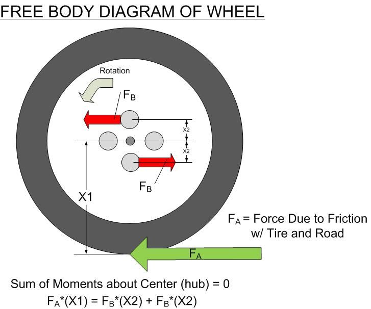 For the non engineering types, a moment is a force multiplied by its distance from the point in question (think of a lever force). We will use the very center of the wheel (hub) as our point of interest to take the moments from and we will assume there is no moment at that point. (it can rotate freely if the right forces are applied). This brings us to the diagram. You have three forces and since the wheel is in static equilibrium (NOT MOVING) these forces need to equal each other. The forces pushing the wheel to rotate in one direction must equal the forces that want to cause it to rotate in the opposite direction. If you can imagine the force due to friction being moved further away from the center of the wheel (like a big truck tire) you can see that (with the equation) it will cause the force needed by each studs to increase to accommodate for this. Looking into material properties and the shear forces on each wheel stud, it would require you to use a larger wheel stud to keep them from shearing off. A second option would be to increase the distance the studs are placed from the center of the wheel. This will help alleviate the shear stress that is place on each lug. At the same time, more lugs can be added now that there is more space between each stud as you move them further from the hub. This is a big part of the reason a large truck has so many lugs and they are so far from the hub. They are all helping to counter act the forces put on the wheel by the friction from the road (which is created by the wheel being torqued by the axles, etc) I hope some of that makes sense... ( I used Microsoft Visio to make that in case you were wondering..) This post has been edited by jcbass7: Oct 7, 2010 - 7:33 PM |
Posts in this topic
 Random_Stranger What is Bolt Pattern? Dec 24, 2009 - 3:29 AM
 Hanyo bolt pattern for rims are the number of studs and ... Dec 24, 2009 - 3:31 AM
 Random_Stranger QUOTE (Hanyo @ Dec 24, 2009 - 12:31 ... Dec 24, 2009 - 3:32 AM Hanyo yup Dec 24, 2009 - 3:35 AM 808celica this makes me wonder who made the decision to use ... Dec 24, 2009 - 3:36 AM Random_Stranger QUOTE (808celica @ Dec 24, 2009 - 12... Dec 24, 2009 - 3:38 AM Hanyo QUOTE (808celica @ Dec 24, 2009 - 12... Dec 24, 2009 - 3:50 AM Random_Stranger QUOTE (Hanyo @ Dec 24, 2009 - 12:50 ... Dec 24, 2009 - 4:17 AM SinisterSinner QUOTE (Hanyo @ Dec 24, 2009 - 5:50 A... Dec 25, 2009 - 11:59 AM SinisterSinner . Dec 25, 2009 - 12:02 PM trdproven 5 lug universal does mean it will fit all 5 lugs. ... Dec 24, 2009 - 11:14 AM garin first number is number of studs second is distance... Dec 25, 2009 - 4:07 PM sunwukongg so 114.3 wont fit? Sep 29, 2010 - 12:26 AM EKAn Sadly no... you can run adapters that change your ... Sep 29, 2010 - 12:33 AM conus00 Some wheels are dual-bolt pattern. Mine (for examp... Sep 29, 2010 - 10:03 AM
 |
1 User(s) are reading this topic (1 Guests and 0 Anonymous Users)
0 Members:
| Lo-Fi Version | Time is now: August 1st, 2026 - 10:44 AM |