
 Oct 28, 2005 - 11:31 PM Oct 28, 2005 - 11:31 PM
|
 
|
 Enthusiast  Joined Oct 10, '03 From Wichita, KS Currently Offline Reputation: 5 (100%) |
1. You will not have a cruise control indicator.
2. You will not have an overdrive off indicator. 3. Wire A13 from the AT200/ST204 will not plug into anything which simply means your brake light won't come on when you're starting the car. 4. Rear foglights indicator will not be used since USDM Celicas do not have them. 5. I have no idea what the indicator is below the rear foglight indicator and therefore will not be used. 6. There are diodes in the rear foglight and mystery indicator circuits. You don't need to worry about them. No need to put bulbs in their sockets either. 7. B13 on the Japanese ST205 combo meter will be directly connected to the MAP sensor from an ST205. 8. Boost gauge circuit is not currently complete. 9. For the sake of simplicity, from here on out, both AT200 and ST205 connectors will use this scheme (as per USDM BGB): A = 13 pin B = 16 pin C = 10 pin  Wires in the column labeled ST204/AT200 will need to be connected to the plug in the column labeled ST205. Japan ST204 AT200---ST205 A01---to---A01 A02---to---B02 A03---to---C05 A04---to---C04 A05---to---C07 A06---to---A04 A07---to---A12 A08---to---A08 A09---to---B04 A10---to---A06 A11---to---NOTHING A12---to---NOTHING A13---to---N/A (BRAKE LIGHT ON WHILE STARTING) B01---to---B01 B02---to---NOTHING B03---to---B03 B04---to---A13 B05---to---NOTHING B06---to---B06 B07---to---B07 B08---to---B08 B09---to---B09 B10---to---B10 B11---to---B11 B12---to---NOTHING B13---to---B14 B14---to---C01 B15---to---B15 B16---to---B16 C01---to---NOTHING C02---to---C02 C03---to---NOTHING C04---to---C03 C05---to---NOTHING C06---to---C08 C07---to---C06 C08---to---N/A (OVERDRIVE) C09---to---N/A (CRUISE) C10---to---C10 ST205 Combo Meter Circuit (Japan):  Australian and European ST205 gauge clusters are different. The pinout information for them is below. The information used to create this part of the how to was from the ST205 BGB at CelicaTech.com Australia ST204 AT200---ST205 A01---to---A02 A02---to---A01 A03---to---?NO SRS LIGHT? A04---to---?NO SRS LIGHT? A05---to---?NO SEATBELT LIGHT? A06---to---B03 A07---to---B05 A08---to---A04 A09---to---B06 A10---to---A09 A11---to---N/A A12---to---N/A A13---to---N/A B01---to---B01 B02---to---N/A B03---to---B02 B04---to---A12 B05---to---N/A B06---to---B07 B07---to---B08 B08---to---B09 B09---to---B10 B10---to---B11 B11---to---B12 B12---to---N/A B13---to---B14 B14---to---C01 B15---to---B15 B16---to---B16 C01---to---N/A C02---to---C03 C03---to---N/A C04---to---C02 C05---to---N/A C06---to---C06 C07---to---C07 C08---to---C08 C09---to---C09 C10---to---C10 ST205 Combo Meter Circuit (Australia) *Remember A=13 pin, B=16 pin, C=10 pin*: 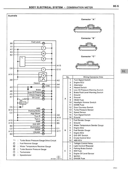 Europe ST204 AT200---ST205 A01---to---A02 A02---to---A01 A03---to---?NO SRS LIGHT? A04---to---?NO SRS LIGHT? A05---to---?NO SEATBELT LIGHT? A06---to---B03 A07---to---B05 A08---to---A04 A09---to---B06 A10---to---A09 A11---to---N/A A12---to---N/A A13---to---N/A B01---to---B01 B02---to---N/A B03---to---B02 B04---to---A12 B05---to---N/A B06---to---B07 B07---to---B08 B08---to---B09 B09---to---B10 B10---to---B11 B11---to---B12 B12---to---N/A B13---to---B14 B14---to---C02 B15---to---B15 B16---to---B16 C01---to---N/A C02---to---C03 C03---to---N/A C04---to---C05 C05---to---N/A C06---to---C07 C07---to---C08 C08---to---N/A (OVERDRIVE) C09---to---N/A (CRUISE) C10---to---C10 ST205 Combo Meter Circuit (Europe) *Remember A=13 pin, B=16 pin, C=10 pin*: 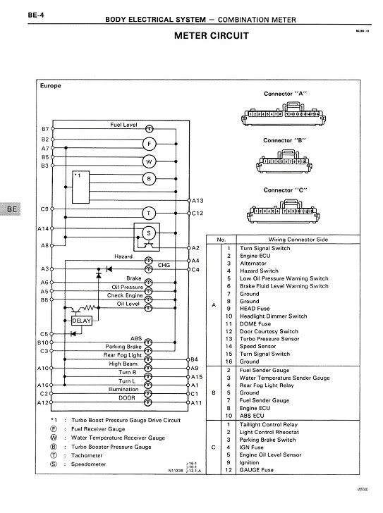
This post has been edited by WannabeGT4: Jan 26, 2006 - 12:46 PM --------------------  Project ST204.5 99.88946% complete... |

Posts in this topic
 WannabeGT4 AT200/ST204 to ST205 Combo Meter How-To Oct 28, 2005 - 11:31 PM
 Valo666 bump..sticky..nice work man. Oct 29, 2005 - 10:36 PM JoKeRkId613 Good work Justin. One question... Where did you ge... Oct 31, 2005 - 12:33 PM WannabeGT4 Yep. I made it myself using the pictures of the ba... Oct 31, 2005 - 3:16 PM devilsden97 i dont understand the "bump" thing that ... Oct 31, 2005 - 5:00 PM JoKeRkId613 They say bump because they want to bump the thread... Oct 31, 2005 - 6:41 PM freddy121389 BUMP BUMP BUMP KUDOS Jul 11, 2009 - 12:44 PM
 WannabeGT4 QUOTE (freddy121389 @ Jul 11, 2009 - 12... Jul 15, 2009 - 3:34 PM tadastoppp I don't really understant for what it is desig... Nov 8, 2009 - 4:00 AM urbandork QUOTE (tadastoppp @ Nov 8, 2009 - 1... Nov 8, 2009 - 2:17 PM Smaay is there any identifying feature to determine if y... Jan 13, 2015 - 4:26 PM WannabeGT4 QUOTE (Smaay @ Jan 13, 2015 - 4:26 P... Jan 13, 2015 - 7:33 PM
  |
1 User(s) are reading this topic (1 Guests and 0 Anonymous Users)
0 Members:
| Lo-Fi Version | Time is now: May 7th, 2024 - 4:16 PM |