
 Nov 3, 2005 - 11:01 AM Nov 3, 2005 - 11:01 AM
|
 
|
|
Enthusiast  Joined Feb 9, '03 From Sioux falls, South Dakota Currently Offline Reputation: 1 (100%) |
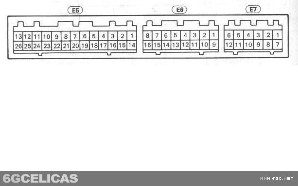
I know this has been covered before and i have searched but i can't get the search function to work right. i need to know, color, pin #, and connector for the speed signal and rpm on a 97 st. According to the how to on the afc the rpm is the 11th pin black an yellow but it doesnt say what direction to count from. if you count the way most manuals do it the 11th pin isnt black and yellow.anything will help thanks in advance.
-Aaron- --------------------  |

 |
Replies
(1 - 11)
|
Nov 3, 2005 - 3:36 PM
|
|
 Enthusiast Joined Oct 10, '03 From Wichita, KS Currently Offline Reputation: 5 (100%) |
 Did the picture he provided not explain it enough? Or is the picture wrong? --------------------  Project ST204.5 99.88946% complete... |
|
Nov 3, 2005 - 6:58 PM
|
|
|
Enthusiast Joined Feb 9, '03 From Sioux falls, South Dakota Currently Offline Reputation: 1 (100%) |
the only wire that is black/yellow would be in pin # 3 so thats why inconfused
-Aaron- -------------------- |
|
Nov 3, 2005 - 7:07 PM
|
|
|
Enthusiast Joined Oct 10, '03 From Wichita, KS Currently Offline Reputation: 5 (100%) |
QUOTE(afroman @ Nov 3, 2005 - 5:58 PM) the only wire that is black/yellow would be in pin # 3 so thats why inconfused -Aaron- [right][snapback]352761[/snapback][/right] If you're looking at the back of the plug count from right to left. If you're looking at the face of the plug count from left to right. Also edo's celica isn't from the US. I'll have to look at the wiring diagram for the US. EDIT: You're right. The USDM wiring diagram shows IGF (Ignition Feedback) as pin #3 black / yellow. If you're needing the SPD wire from the ECU it is pin #9 on your 22 pin connector either green or orange. Also, I just noticed you've got a 97 (OBDII) that might make a difference. Not sure since I don't have the wiring diagrams for it. This post has been edited by WannabeGT4: Nov 3, 2005 - 7:33 PM -------------------- Project ST204.5 99.88946% complete... |
|
Nov 3, 2005 - 7:35 PM
|
|
|
Enthusiast Joined Feb 9, '03 From Sioux falls, South Dakota Currently Offline Reputation: 1 (100%) |
thanks so much. i took a chance and tapped the black/yellow wire anyway and it seems to work so who knows. if you look at the plug whiel plugged in its the 11th wire from the left.. thanks again for the spd wire.
-Aaron- -------------------- |
|
Nov 3, 2005 - 7:40 PM
|
|
|
Enthusiast Joined Oct 10, '03 From Wichita, KS Currently Offline Reputation: 5 (100%) |
No problem. Anytime.
-------------------- Project ST204.5 99.88946% complete... |
|
Nov 3, 2005 - 9:24 PM
|
|
|
Enthusiast Joined Feb 9, '03 From Sioux falls, South Dakota Currently Offline Reputation: 1 (100%) |
 looking at this it says that pin 11 on connector E7 is the spd sensor and that pin 9 is for RSC IAC valve. i just tried both and neither of them work. so i dont know what up. -Aaron- -------------------- |
|
Nov 3, 2005 - 10:07 PM
|
|
|
Enthusiast Joined Oct 10, '03 From Wichita, KS Currently Offline Reputation: 5 (100%) |
That's for a manual transmision car. Don't you have an automatic? The speed sensor should be on your 22pin connector. If you're looking at the back of the plug it will be on the top row third from the left. You shouldn't even have a 12 pin connector.
-------------------- Project ST204.5 99.88946% complete... |
|
Nov 4, 2005 - 11:19 AM
|
|
|
Enthusiast Joined Oct 10, '03 From Wichita, KS Currently Offline Reputation: 5 (100%) |
any luck?
-------------------- Project ST204.5 99.88946% complete... |
|
Jun 28, 2007 - 1:07 PM
|
|
|
Enthusiast Joined Mar 30, '05 From Wisconsin Currently Offline Reputation: 0 (0%) |
i got question too?
i try to put timer on my too, but i donno where is (Ignition Live #1) is location where. i thought that be in the key hole, they has four wire is connect to key, i Don't know which one. Red - 12 Volt + (Battery) Black - Ground (Negative) Yellow - Ignition Live #1 Blue - Speed Signal Brown - RPM This post has been edited by funnys_tears: Jun 28, 2007 - 1:09 PM |
|
Jun 28, 2007 - 1:36 PM
|
|
|
Enthusiast Joined Aug 31, '02 From Philadelphia, PA Currently Offline Reputation: 8 (100%) |
you should make things easy and just buy a harness for it . any st205 harness will work.
-------------------- 15PSI - 30MPG - Megasquirt Tuned
|
|
Jun 28, 2007 - 1:58 PM
|
|
|
Enthusiast Joined Mar 17, '05 From The Netherlands Currently Offline Reputation: 0 (0%) |
QUOTE(lagos @ Jun 28, 2007 - 8:36 PM) [snapback]573220[/snapback] you should make things easy and just buy a harness for it . any st205 harness will work. Or MK IV Supra harness. Uses the same generation plugs/connectors in the entire car. -------------------- JDM Powerplant installed, BPU coming very soon!
 |
 |
1 User(s) are reading this topic (1 Guests and 0 Anonymous Users)
0 Members:
| Lo-Fi Version | Time is now: June 23rd, 2026 - 12:52 PM |