Installing an Apexi S-AFC II on the ST
| Author: | edo17982 |
| Approximate Time: | 2 Hours |
| Required Tools: | Isolant tape Scissors Wire stripper |
This how-to article details how to install an Apexi S-AFC II onto your Celica ST(AT200).
First, disconnect your battery to avoid any short circuit to the ECU.
Now, on the passenger side of the interior, remove the glovebox next to the central console. Now you should see the ECU. Disconnect the three connectors from the ECU. The first connector has 26 outputs (E5), the second 16 outputs (E6) and the third 12 outputs (E7). Open the Apexi wiring manual to the page with the wiring diagram T4-B.
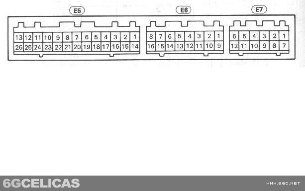 1st Connector (E5)
RPM signal wire: In the ECU connector, this wire is the 11th in the upper row marked BLACK and YELLOW. Now you need to strip 5mm of insulation from this ECU wire. Once you've done it, attach the GREEN wire of the S-AFC connector to the uncovered part of the ECU wire as shown on Apexi instructions. Now cover the wiring point with isolant tape.
Ground wire: In the ECU connector, this wire is the 3rd in the lower row marked BROWN. Now you need to strip 5mm of insulation from this ECU wire in 2 points, separated by 1cm. Once you've done it, attach the BROWN wire of the S-AFC connector to the uncovered ECU wire from the ECU side. Then attach the BLACK wire of the S-AFC connector to the uncovered ECU wire from the non-ECU side. Now cover the wiring points with isolant tape.
2nd Connector (E6)
MAP sensor wire: In the ECU connector this wire is the 7th in the upper row marked GRAY and BLACK. Now you need to cut the wire and apply the MALE fitting provided with the AFC to the cut wire in the ECU side. Apply the FEMALE fitting to the non-ECU side cut wire. Now simply connect the YELLOW wire of the S-AFC connector to the ECU side and the WHITE wire of the S-AFC connector to the non-ECU side.
TPS sensor wire: In the ECU connector this wire is the 7th in the lower row marked BLACK and WHITE. Now you need to remove 5mm of insulation from this ECU wire. Once you've done it, fix the GRAY wire of the S-AFC connector to the uncovered part of the ECU wire as shown on Apexi instructions. Now cover the wiring point with isolant tape.
KNK wire: In the ECU connector, this wire is the 3rd in the lower row marked WHITE but a bit transparent. You need to remove 5mm of insulation from this ECU wire. Once you've done it, connect the PURPLE wire of the S-AFC connector to the uncovered part of the ECU wire as shown on Apexi instructions. Now cover the wiring point with isolant tape.
3rd Connector (E7)
 IG power: In the ECU, this wire is the last in the lower row marked BLACK and YELLOW. You need to remove 5mm of insulation from this ECU wire. Once you've done it, fix the RED wire of the S-AFC connector to the uncovered part of the ECU wire as shown on Apexi instructions. Now cover the wiring point with isolant tape.
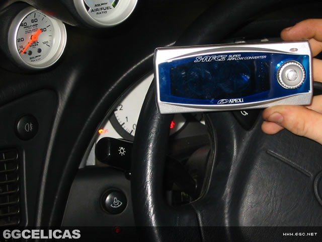
Now most of the hard work is done. Re-connect your battery, turn the ignition to on, and you'll see the S-AFC turning on. If you hear any unusual sound or smell from the ECU, Immediately turn off your car and disconnect your battery, because maybe you have a short circuit. If this happens, double and triple check all of the wiring until you find the problem.
If everything is working, you simply need to program the S-AFC II and enjoy! If you have any questions, PM or email me, and I'll be happy to help you.